Overview
This tutorial was made in Blender 5.1.
This is what we will build:
A Grease Pencil tail that follows an object. The tail is colored by the speed of that object. Blue means slow, red means fast.
You can either follow this tutorial step by step, or download the ready-made Blender file here: Download Blender File (.blend)
Getting Started
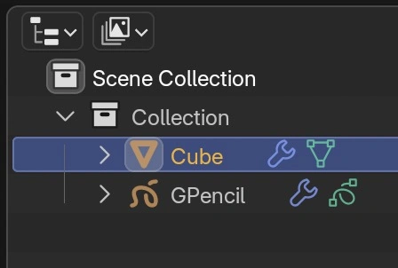
First, start with a default cube and an empty Grease Pencil object.
Next, add a Geometry Nodes modifier with the “Speed Tail” node group to the Grease Pencil object.
Normally, this is where a tutorial would show node trees that you’d have to tediously recreate from screenshots.
But there’s a better way with Tree Clipper!
Tree Clipper is a free Blender extension for copying and pasting node trees between files. Install it here, then use the button below to copy the “Speed Tail” node tree to your clipboard.
 The setup works the following way:
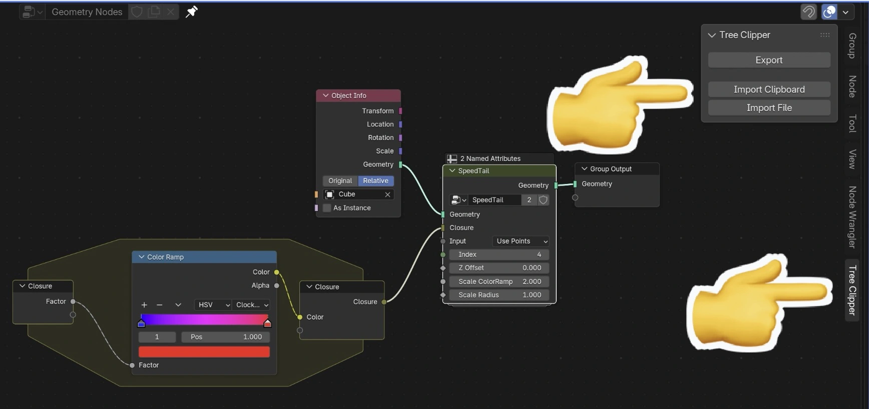
- Add a new Geometry Nodes modifier to the empty Grease Pencil object.
- Open the N-panel sidebar and press Import Clipboard to import the SpeedTail node group.
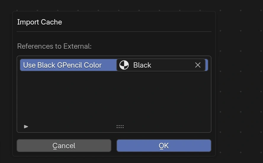
- Select a Grease Pencil material (e.g., “Black”) in the pop-up window. It must be a GP material, not a regular material.
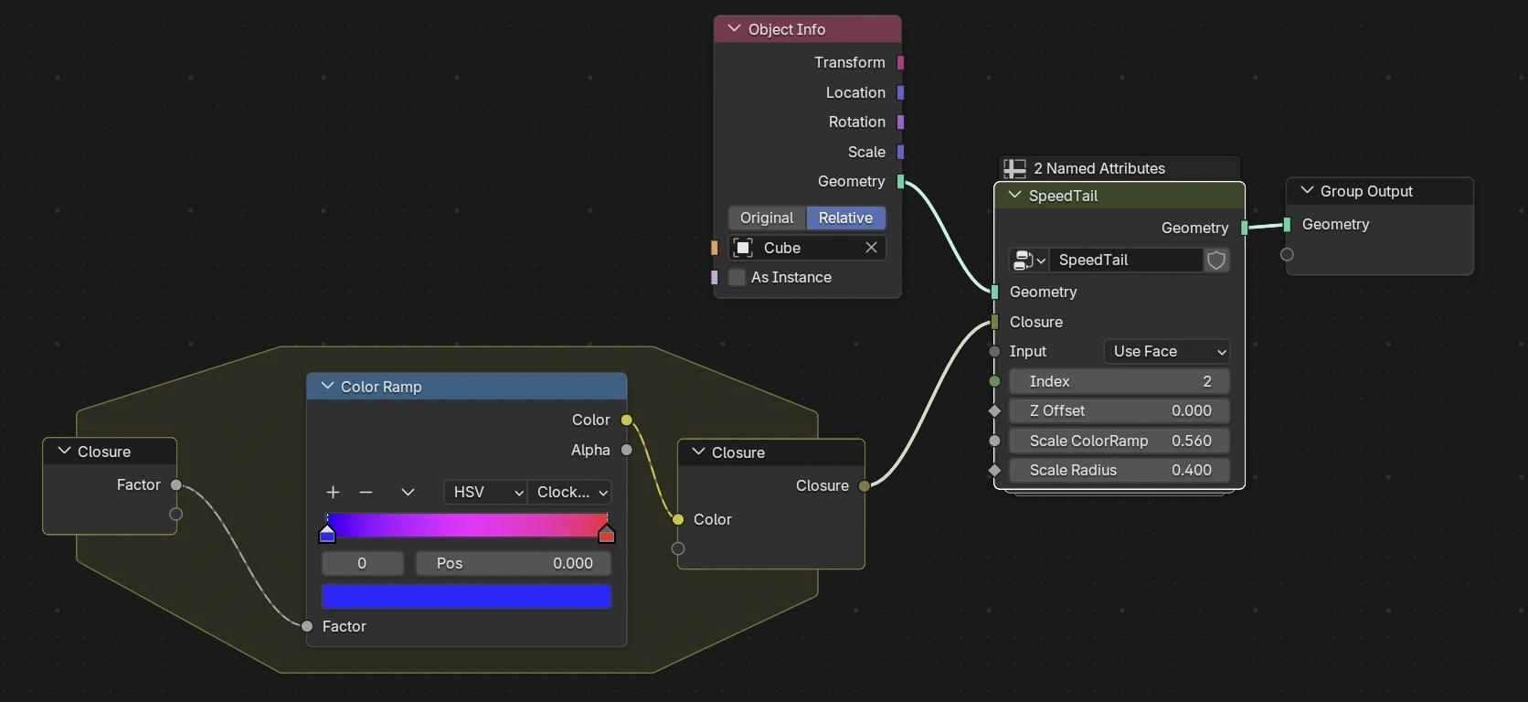
- Set up the rest of the node tree:
- Add an Object Info node with the cube.
- Add a Closure zone and add the Color Ramp in the middle.
- Connect everything as shown in the above screenshot.
A note on the Closure zone: The Color Ramp is used internally inside the SpeedTail node group, but we want it to be accessible from the root tree so we can customize the colors. That’s what the Closure zone is for: it “teleports” the Color Ramp into the right place inside SpeedTail without breaking the node group encapsulation.
Tweak Parameters
Now we can tweak the parameters in the “Speed Tail” node.
- Input: use
PointsorFacedomain - Index: choose one index where the curve starts.
- Scale Radius: the radius of the curve
Adjust the Color Ramp to customize the color gradient.
Because we are using a Simulation Zone, we can now move to frame 1, press play, and move the object. The tail will follow.
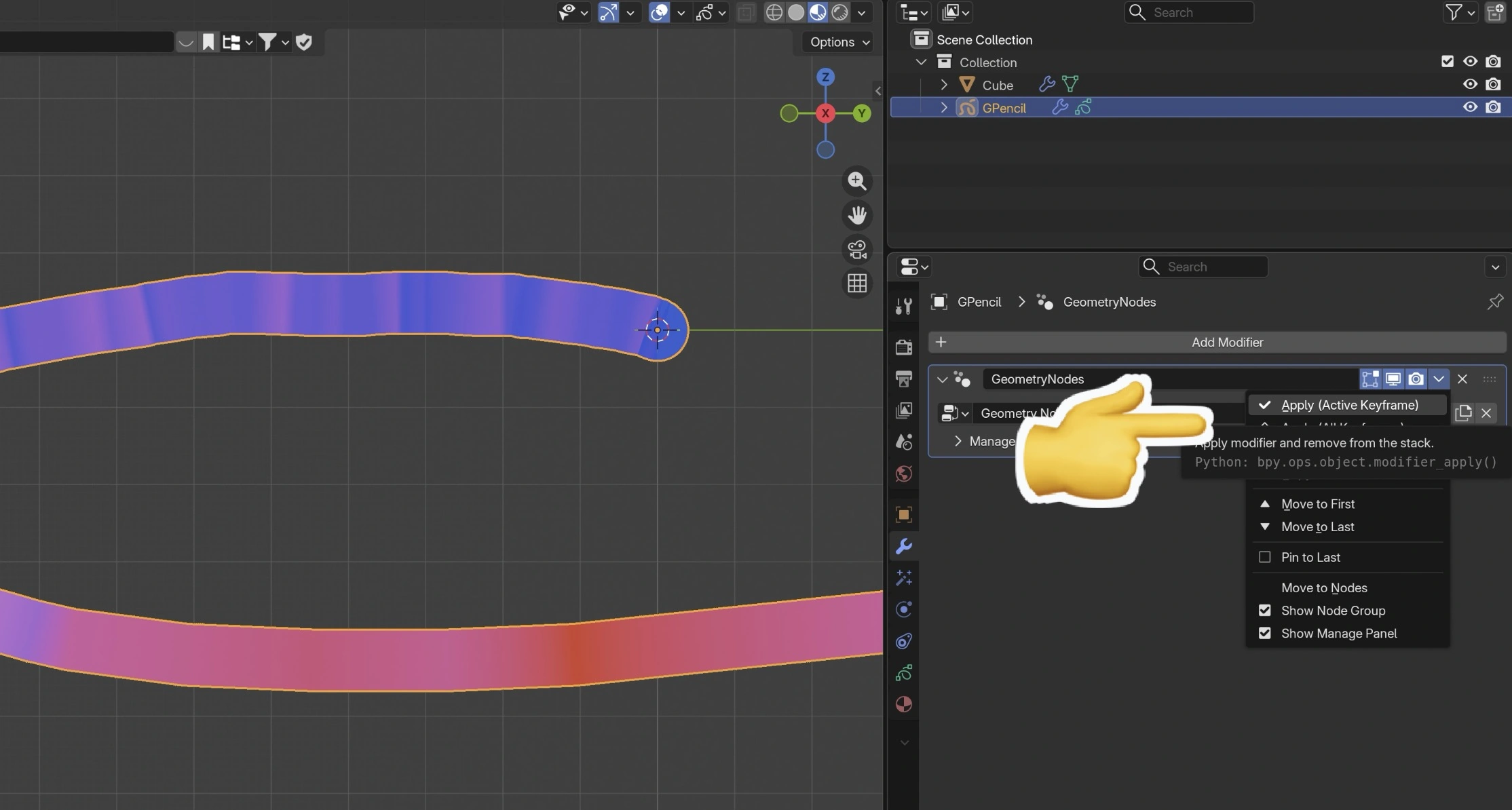
If we want to keep this tail, we can pause the simulation, go to the modifier tab, and press Apply (Active Keyframe). The tail will then persist.
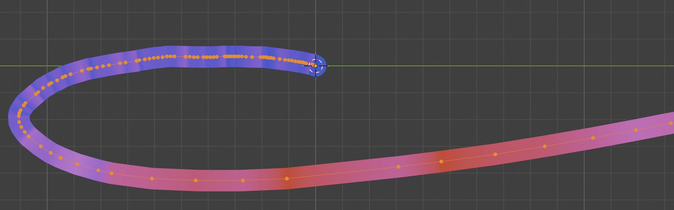
In edit mode, we can even see the spacing of the points.
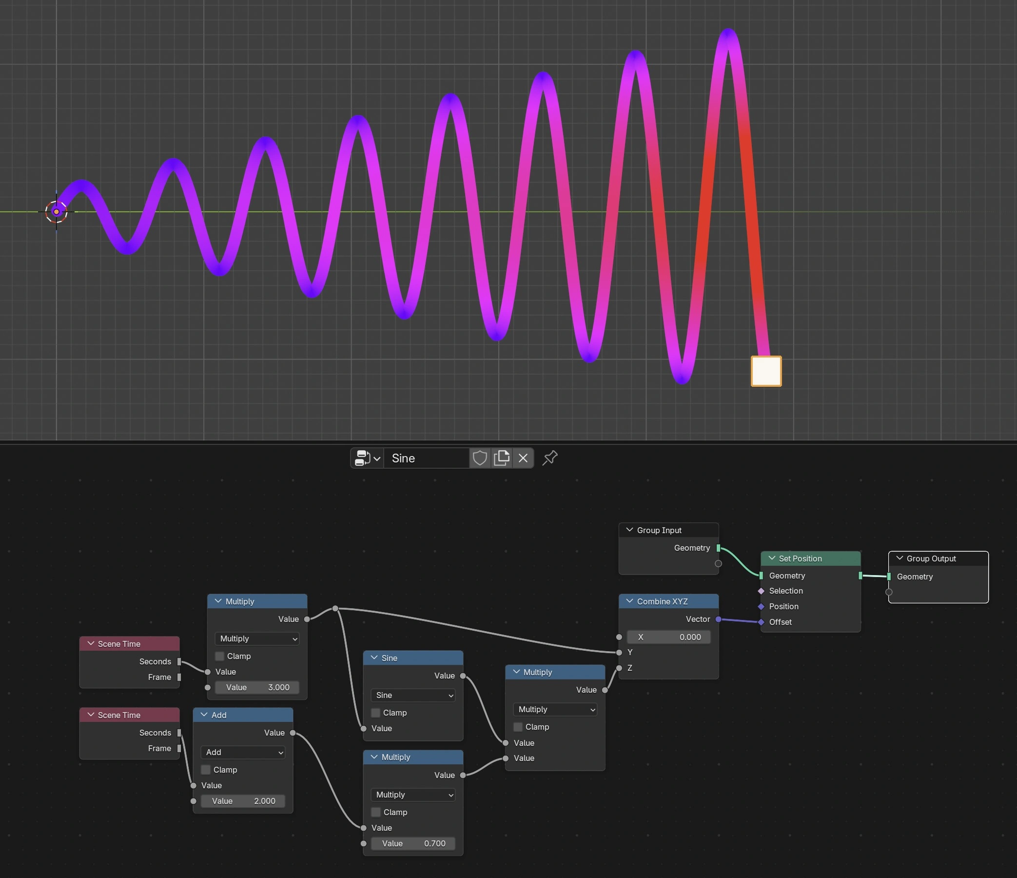
We can now add this sine wave via geonodes modifier to the cube and get this beautiful time-dependent tail.
Download Blender File (.blend)
How It Works
Now we have everything in place, and it’s ready to use. In this chapter, we will take a closer look at how it all works.
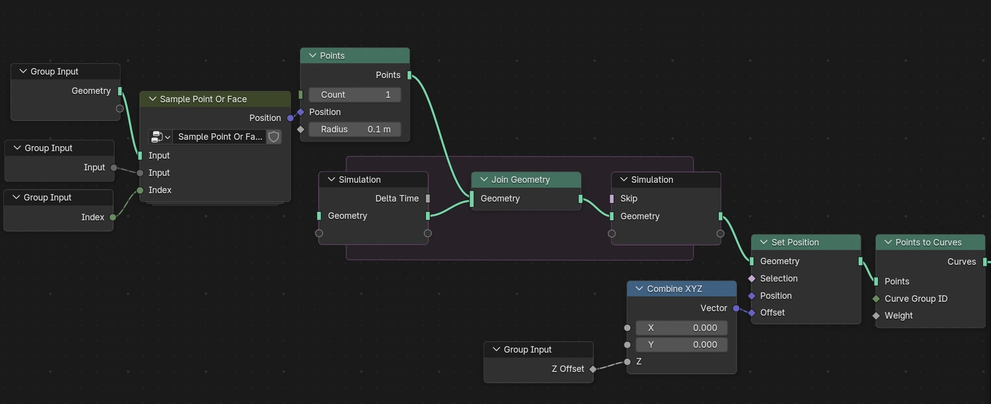
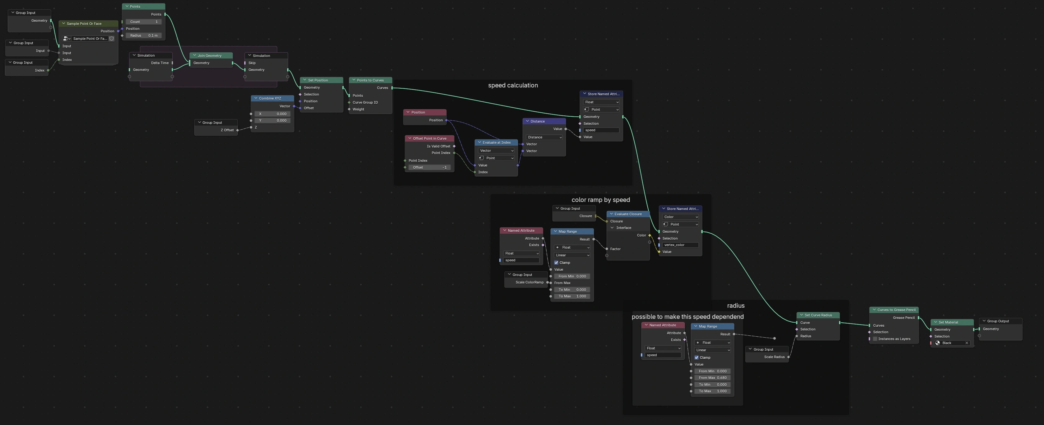
This first part of the SpeedTail node group is responsible for getting the correct position. We append points one by one into a mesh via Join Geometry inside a Simulation Zone. Every frame adds one point.
After that, the mesh is converted into a curve.
In the next part, we calculate the distance between neighboring points along the curve. This is done with the Offset Point in Curve node together with a Distance math node. The farther apart the points on the curve are, the higher the speed.
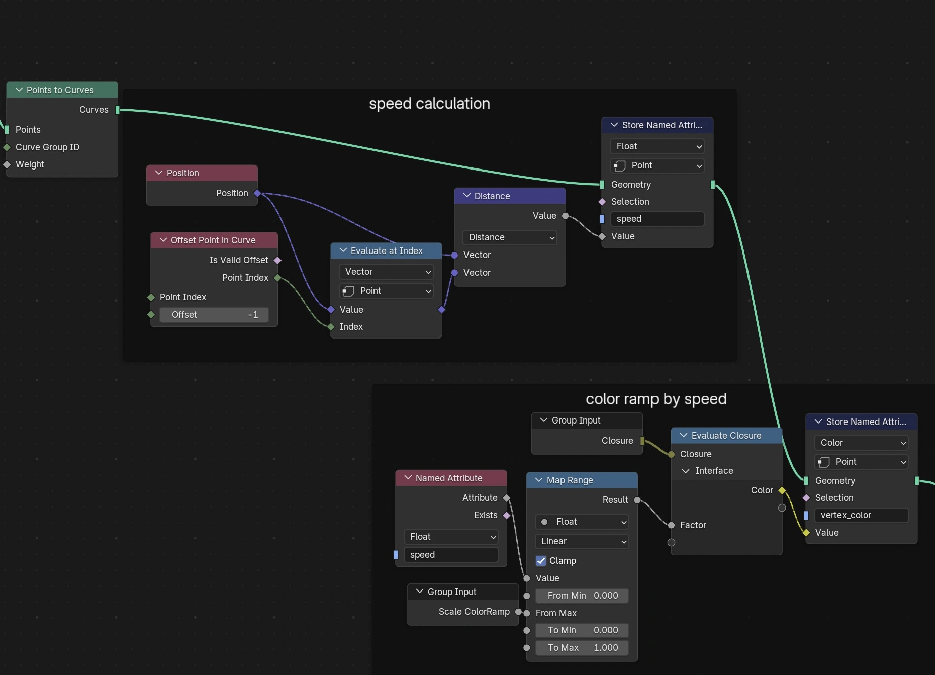
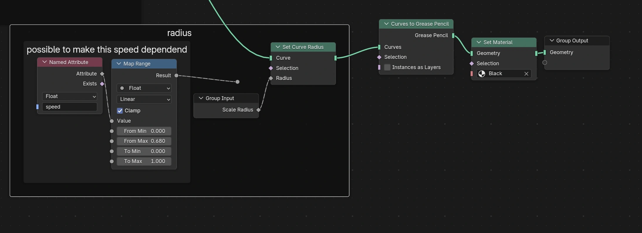
And finally, we add the radius to the curve. Optionally, the radius can also depend on the speed.
Full node tree:
Final Notes
I also tried building another version that uses the Grease Pencil object’s Group Input directly, so there is no additional Object Info node and no Simulation Zone.
At first, that seemed like a good idea, and it even works because Geometry Nodes on Grease Pencil objects are evaluated while drawing. Very cool!
But in practice, it’s not a great fit for motion trails because of these two drawbacks:
- While drawing Grease Pencil strokes, the sampling of points along the curve is not speed dependent. The points stay evenly spaced, even if some parts were drawn quickly and others slowly.
- While drawing, Grease Pencil uses a very high stroke resolution. In my case, I had about 3k control points while drawing a single stroke. After the drawing is finished, those control points are reduced to a much smaller number, around 50 in my case. This behavior can be adjusted in
Draw->Nside panel ->Tool->Post-Processing, but still, the simulation zone seems to be the better way.